Some notes on how to use FreeRTOS with a FRDM-KL25Z (almost) without Processor Expert

After a pause while I waited for new hardware to arrive and enough free time to play with it I returned to experimenting with my FRDM-KL25Z. After having tried both the Mbed library and Processor Expert I thought it was time to remove the training wheels and learn to use this thing properly. Both Mbed and PE have their uses, but they hide many important details about how the device functions that I need to know. After figuring out how to configure GPIO pins manually (I recommend this series of articles if you want a gentle introduction to how to use clocks and GPIO pins on the KL25Z) and writing a simple program in C++ (C is a good language, but C++ is so much easier to work with) the only thing I was missing was FreeRTOS. This will not be a complete guide to installing FreeRTOS. I will refer you to other guides that can take you through that part.  These are only a few notes and suggestions that should help you avoid some of my mistakes.

As you may already know, there is no official port of FreeRTOS for the Kinetis L series of ARM Cortex M0+ MCUs. Fortunately there is an unofficial port by Erich Styger. The bad news is that the port is built around PE, and your will need to set it up together with Eclipse if you want to use FreeRTOS. The good news is that you only need to use it once and export the necessary code. Once you are done you can use whatever development tools you want.

Before you go any further you must follow Styger’s instructions for how to set up PE with Eclipse, and while it isn’t necessary you should also read his instructions for setting up and configuring FreeRTOS with PE. Play around with it. Make sure that it is working. Then read his instructions for generating static code from the FreeRTOS PE component that can be extracted and used on its own.

If you follow the instructions you will be left with a folder with all FreeRTOS code. Now comes the tricky part: using it in a project without PE. The exact details will depend on the tools and libraries you are using. In my case I wanted to create a C++ project in Eclipse using the GCC-ARM Eclipse plugin. I will go through some of the steps I had to take to get it to work and point out a few things that gave me trouble.

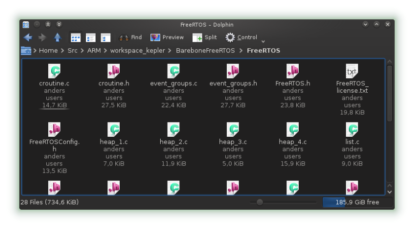
Once you have created a static copy of the FreeRTOS code,  move it into your new project.folders1

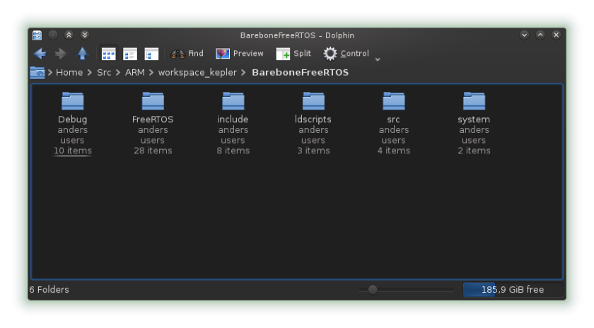
I put all FreeRTOS files in one folder to simplify things.

freertos_folder1

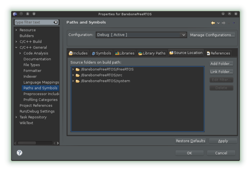
Open the project properties and make the FreeRTOS folder a source folder.

include1

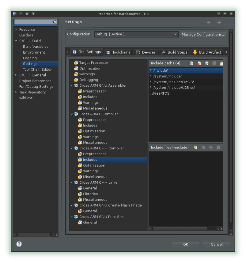
Go to the build settings and also add the folder to the include path.

source_folder1

This should be enough for Eclipse to find all the new files, but if you now try to compile it you will get a long list of errors. Most of these are simple things that are easily fixed.

Getting interrupts to work was the hardest part. It is quite simple once you know what the problem is, but it was not obvious. The FreeRTOS code you have is set up to use the interrupt handlers and interrupt vectors created by other PE components. Since you do not have those components you must modify some parts of the code.

First, copy the ‘Events.h’ and ‘Events.c’ files from your PE project, remove all interrupt handlers not starting with FRTOS_ (assuming there are any), and then remove the FRTOS_ part of all function names (e.g. vApplicationIdleHook instead of FRTOS_vApplicationIdleHook). Do a search through all your other FreeRTOS code and do the same there (or wait for the compiler to complain). Some function names will be incorrect. If you are using C++ also make sure that the event files are enclosed within extern blocks. They will be used both by FreeRTOS’s C code and your C++ code.

#ifdef __cplusplus
extern "C" {
#endif

...

#ifdef __cplusplus
}
#endif

Next, if you are not using the interrupt vector you got from PE and instead uses the one from the GCC-ARM plugin (‘vectors_MKL25Z.c’), then you will have to change some function names. FreeRTOS uses a couple of interrupt handlers.

  • SysTick_Handler
  • SVC_Handler
  • PendSV_Handler

Your FreeRTOS code and ‘vectors_MKL25Z.c’ will use different names for these interrupt handlers. This must be fixed.

In ‘portmacro.h’, replace the lines 291-293

void vPortSVCHandler(void); /* SVC interrupt handler */
void vPortPendSVHandler(void); /* PendSV interrupt handler */
void vPortTickHandler(void); /* Systick interrupt handler */

with

void SVC_Handler(void); /* SVC interrupt handler */
void PendSV_Handler(void); /* PendSV interrupt handler */
void SysTick_Handler(void); /* Systick interrupt handler */

In ‘port.h’, replace line 727

void vPortTickHandler(void) {

with

void SysTick_Handler(void) {

The line 848

__attribute__ ((naked)) void vPortSVCHandler(void) {

with

__attribute__ ((naked)) void SVC_Handler(void) {

And the line 999

__attribute__ ((naked)) void vPortPendSVHandler(void) {

with

__attribute__ ((naked)) void PendSV_Handler(void) {

The rest should be easy. There will be some inclusions of header files to remove and some that must be added, and a few function and variable names will be wrong. You also have to configure FreeRTOS (unless you did so before exporting the code). This is done in the ‘FreeRTOSConfig.h file’. Refer to FreeRTOS’s documentation for more information about that part.

How to use the serial interface to communicate with an FRDM-KL25Z in Linux

This short guide will show how to communicate with the FRDM-KL25Z using the Serial and USBSerial classes from the mbed library in Linux.

Serial and USBSerial are two different methods for creating serial connections using mbed. USBSerial creates an emulated serial port over a normal USB port while Serial uses the built in serial port (if there is one). In the case of the FRDM-KL25Z  this can be done through the virtual serial port provided by OpenSDA.

This small example will create two serial connections; one using the serial port built into OpenSDA, and one over the normal USB port. It will pass everything given to either interface on to the other interface.

#include <mbed.h>
#include <USBSerial.h>

Serial debug(USBTX, USBRX);
USBSerial usb;

int main()
{
  while(1) {
    if(usb.readable()) {
      debug.putc(usb.getc());
    }
    if(debug.readable()) {
      usb.putc(debug.getc());
    }
  }
}

Compile the code and load it onto your FRDM-KL25Z, then  connect it to your computer using both USB ports and run the following command.

ls -l /dev/ttyACM*

Your output should look something like this.

crw-rw---- 1 root dialout 166, 0 Aug 19 13:56 /dev/ttyACM0
crw-rw---- 1 root dialout 166, 1 Aug 19 14:19 /dev/ttyACM1

Each of these device files are connected to one of the serial interfaces on the FRDM-KL25Z. To use them you will first have to add your user to the dialout group.

sudo usermod -a -G dialout USERNAME

You can use any terminal emulator of your choice to connect to these serial ports. I will be using minicom for this example.

Open two terminals. On the first run:

minicom -b 9600 -D /dev/ttyACM0

And in the second:

minicom -b 9600 -D /dev/ttyACM1

‘-b 9600’ sets the baud rate. The default value used by mbed is 9600.

If everything is working correctly whatever you write in one terminal should now appear on the other, and vice versa. If it doesn’t create new lines when you press ‘enter’ and it instead jumps to the beginning of the current line, tell minicom to add linefeeds by pressing ‘Ctrl-a a’.

A step-by-step guide to using the FRDM-KL25Z in Linux with GCC and the mbed library

Freescale FRDM-KL25Z
By Viswesr (Own work) [CC-BY-SA-3.0 (http://creativecommons.org/licenses/by-sa/3.0)%5D, via Wikimedia Commons
I recently bought a Freescale FRDM-KL25Z to experiment with ARM and embedded systems programming, and I thought I should share my experiences with using it in a completely open source Linux environment so that others may learn from my (many) mistakes. The FRDM-KL25Z is an inexpensive development platform built around an ARM Cortex M0+ based microcontroller.  It has support from several commercial development environments, but there is a lack of documentation for how to make it work on Linux using nothing but open source software. After some research, trial and error, and almost bricking the thing, I finally got everything to work.

This post will show you how to set up a development environment around the FRDM-KL25Z using the GCC toolchain and mbed library. To make it more general I will not use any IDE. This will all be by hand. Once you have it working it should not be a problem

I had to buy a freedom board for a school class, and I was frustrated at first to find that there was no support for the linux platform. I'm personally a fan of the teensy ARM microprocessors which are supported by GCC or the Arduino IDE, now I can add the new micro to my growing collection. Thanks again for the great article!

to set up an IDE around it as well, but that is left as an exercise to the reader.

Getting everything to work will require a few steps.

  1. Install the mbed firmware
  2. Install the GCC ARM toolchain
  3. Set up debugging tools
  4. Download and build the mbed library
  5. Create a simple program

Installing the mbed firmware

There are several firmware variants you can install on your FRDM-KL25Z. You can use whichever version you like as long as it supports the CMSIS-DAP debugging interface (i.e. any firmware other than what came pre-installed). The one I have chosen to use is the mbed firmware. It is easy to use and performs a sanity check on any binaries you give it to make sure that you don’t accidentally brick your device (which you very well might do if you are not careful).

To install the mbed firmware first download the newest version. At the moment  (2014-08-13) that would be this one.

Start the board in bootloader mode by holding down the reset button while plugging in the board using the SDA USB port.https://mbed.org/handbook/CMSIS-DAP

A mass-storage device named BOOTLOADER will appear. If you were using Windows it would be enough to copy the firmware file to this device and restart the board, but since you are using Linux it isn’t quite that simple. You first have to mount it using the ‘msdos’ file system type.

sudo mount -t msdos /dev/sdd /mnt

In my case the board shows up as /dev/sdd. This may, of course, be different in your case. Copy the firmware file to /mnt and restart the board. You should now see a mass-storage device named MBED.

To test that everything is working you can try one of mbed’s example programs. Sign in or create an account and click “Import Program”. This will take you to their online IDE where you can export the program to a ‘.bin’. Copy this file to the MBED  device and press the reset button. If everything is working then the led will probably start blinking (depending on the example you chose).

You could stop here and just use mbed’s online IDE. The rest of this guide will show you how to compile your own programs offline with GCC and the mbed library, and how to get the USB debugging interface to work.

Install the GCC ARM toolchain

The next step is to install the tools needed to compile your own programs. For this you want the gcc-arm-none-eabi from launchpad. Download the one ending with linux.tar.bz2, unless you want to compile it from source.

Just extract it somewhere, add the bin directory to you path variable, and you are done.

Set up debugging tools

With any new firmware the FRDM-KL25Z will support USB debugging using the CMSIS-DAP debugging interface. To use it we need to install OpenOCD and hidapi.

First you must download and install hidapi.

git clone http://github.com/signal11/hidapi.git
cd hidapi
./bootstrap
./configure
make
sudo make install

Next, do the same for OpenOCD.

git clone http://openocd.zylin.com/openocd
cd openocd
./bootstrap
./configure --enable-maintainer-mode --enable-cmsis-dap --enable-hidapi-libusb

Open ‘tcl/target/kl25.cfg’ and add the following text to the end.

adapter_khz 50
$_TARGETNAME configure -event gdb-attach {
    halt
}
make
sudo make install

Permissions

By default only the root user has access to the device files used for debugging. If you want to give a normal user permission to use the debugging tools you will have to set up some udev rules.

Create the file ‘/etc/udev/rules.d/45-mbed_debugger.rules’ and add the following to it.

SUBSYSTEM=="usb", ATTR{idVendor}=="0d28", ATTR{idProduct}=="0204", MODE="0660", GROUP="plugdev"

Similarly, create the file ‘/etc/udev/rules.d/99-hidraw-permissions.rules’ and add the following to it.

KERNEL=="hidraw*", SUBSYSTEM=="hidraw", MODE="0664", GROUP="plugdev"

This will give all users in the ‘plugdev’ group read and write access to all relevant device files. You could use any group you want, or just a specific user.

To test that it is working run the following command as a non-privileged user with the FRDM-KL25Z plugged in.

openocd -c "interface cmsis-dap" -f /usr/local/share/openocd/scripts/target/kl25.cfg

If it complains about not finding the libhidapi-hidraw.so.0 library check that ‘/usr/local/lib’ is in ‘/etc/ld.so.conf’, run ‘ldconfig’, and try again.

If you now open a second terminal you should be able to connect to the device with GDB.

arm-none-eabi-gdb --eval-command "target remote localhost:3333"

Download and build the mbed library

The mbed development platform consists of an online browser based IDE and compiler (as you saw earlier), and an open source library that simplifies the development of embedded systems code by hiding low level details from the programmer. This is part we want. To use the library offline without the IDE you will have to  download and compile the source code.

git clone https://github.com/mbedmicro/mbed.git
cd mbed/workspace_tools

In addition to the main mbed library, the repository contains a number of other useful libraries that can be installed.

–rtos Real Time Operating System
–usb USBDevice
–dsp Digital Signal Processing
–fat SDFileSystem

The following command will build the mbed library and all the optional libraries that are compatible with the FRDM-KL25Z.

python build.py -m KL25Z -t GCC_ARM --rtos --usb --dsp --fat

When it is done you can find the compiled libraries in ‘build’. Move them to where you want the mbed libraries to be located.

Create a simple program

Finally everything that you need to build your own programs is in place, but before you can start programming we will have to pull all of the pieces together and show how to compile a program from source code. For this example we will, of course, create a simple program that turns the three LEDs on and off.

Most of the work needed to build a program for the FRDM-KL35Z has already been taken care of for you by the mbed library. All you must do is link everything together and compile it. You could set this up by hand, but I recommend you start out by using this makefile. It will set up all the paths and include directories for you. What is left is to set the path to the mbed libraries in MBED_PATH, set the program name in TARGET,  add any local source and header folders to SRC_DIRS and INC_DIRS, and to tell it which mbed libraries to use.

Next, create the file ‘src/main.cpp’ and add the following to it.

#include <mbed.h>

Ticker tick;

DigitalOut led1(LED_RED);
DigitalOut led2(LED_GREEN);
DigitalOut led3(LED_BLUE);

void flip() {
    led3 = !led3;
}

int main()
{
    led3 = true;

    //Flip the blue LED every 5 seconds
    tick.attach(&flip, 5.0);

    //Flip the red and green LED once every second
    while (true) {
        led1 = true;
        led2 = false;
        wait (1.0);
        led1 = false;
        led2 = true;
        wait (1.0);
    }
}

Don’t forget to add the ‘src’ folder to SRC_DIRS in the makefile, then compile with ‘make’.

If everything is working as it should it should now create a ‘build’ directory with the file ‘mbed.bin’ in it (assuming you did not change TARGET). Copy this file to the MBED device, wait for it to load it, and then press the reset button. The LED should now start blinking in different colors.

That’s all. You are now ready to start programming your own programs. Build something interesting.

Some helpful tips on how not to lock your FRDM-KL25Z and save yourself much pain

Unless you are careful you will sooner or later manage to “lock” your FRDM-KL25Z. This happens when you accidentally enable the security bits. If you have not set up the mbed library (in particular the *.ld files) correctly then this could happen very easily. The mbed firmware will protect you from this mistake by refusing to flash binaries with the security bits enabled, but there are ways to bypass it using the debugger and OpenOCD.

To check if you have set the security bits open the binary in a hex editor and look at the contents of address 0x0000040C. The last two bits should be “10”. If it isn’t, something is wrong and you should NOT attempt to flash this binary to the board. Seriously, don’t do it!

If you ignored my advice and flashed the board with a binary that had the security bits enabled then you will have to unsecure it. This can be a little complicated, but if you read these instructions and still didn’t follow my advice then it’s your own fault. Supposedly there are tools you can use to unsecure the device, but I have not found any that are free and works in Linux. Fortunately, some variants of the FRDM-KL25Z firmware will unset the security bits when they are installed. You can then reinstall the firmware you want to use. This can require some trial and error, but I have had success with the MSD-DEBUG-FRDM-KL25Z_Pemicro_v114.SDA firmware.

Save yourself a lot of trouble and make sure that you don’t do this in the first place. Unless you know what you are doing only program the device by copying binaries to the MBED mass-storage device.

Sources

http://mbed.org/handbook/Firmware-FRDM-KL25Z
http://karibe.co.ke/2013/08/setting-up-linux-opensource-build-and-debug-tools-for-freescale-freedom-board-frdm-kl25z/
http://embeddedworldweb.blogspot.se/2013/08/mbed-gcc-with-eclipse-kl25z-part-1.html
http://mcuoneclipse.com/2012/11/04/how-not-to-secure-my-microcontroller/

Design a site like this with WordPress.com
Get started